Fins and Nose Cone Prep Work
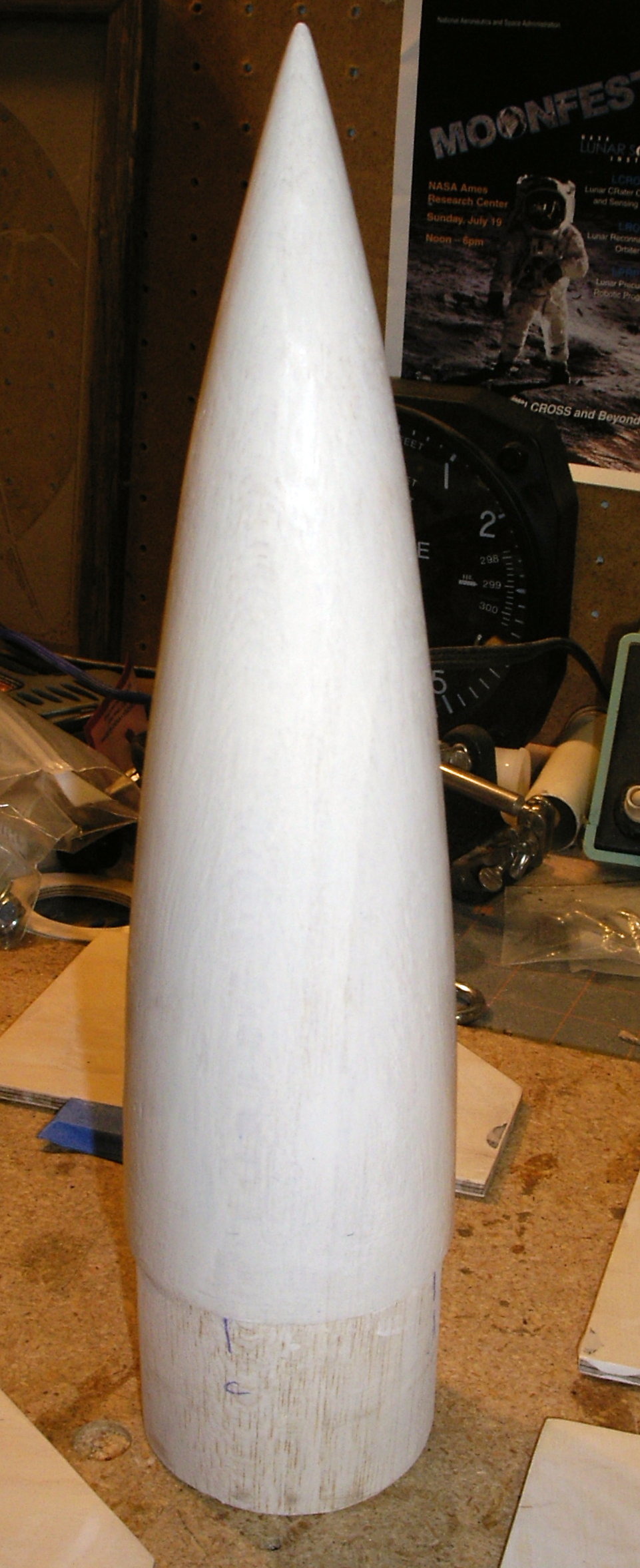
Nose cone undergoing surface prep
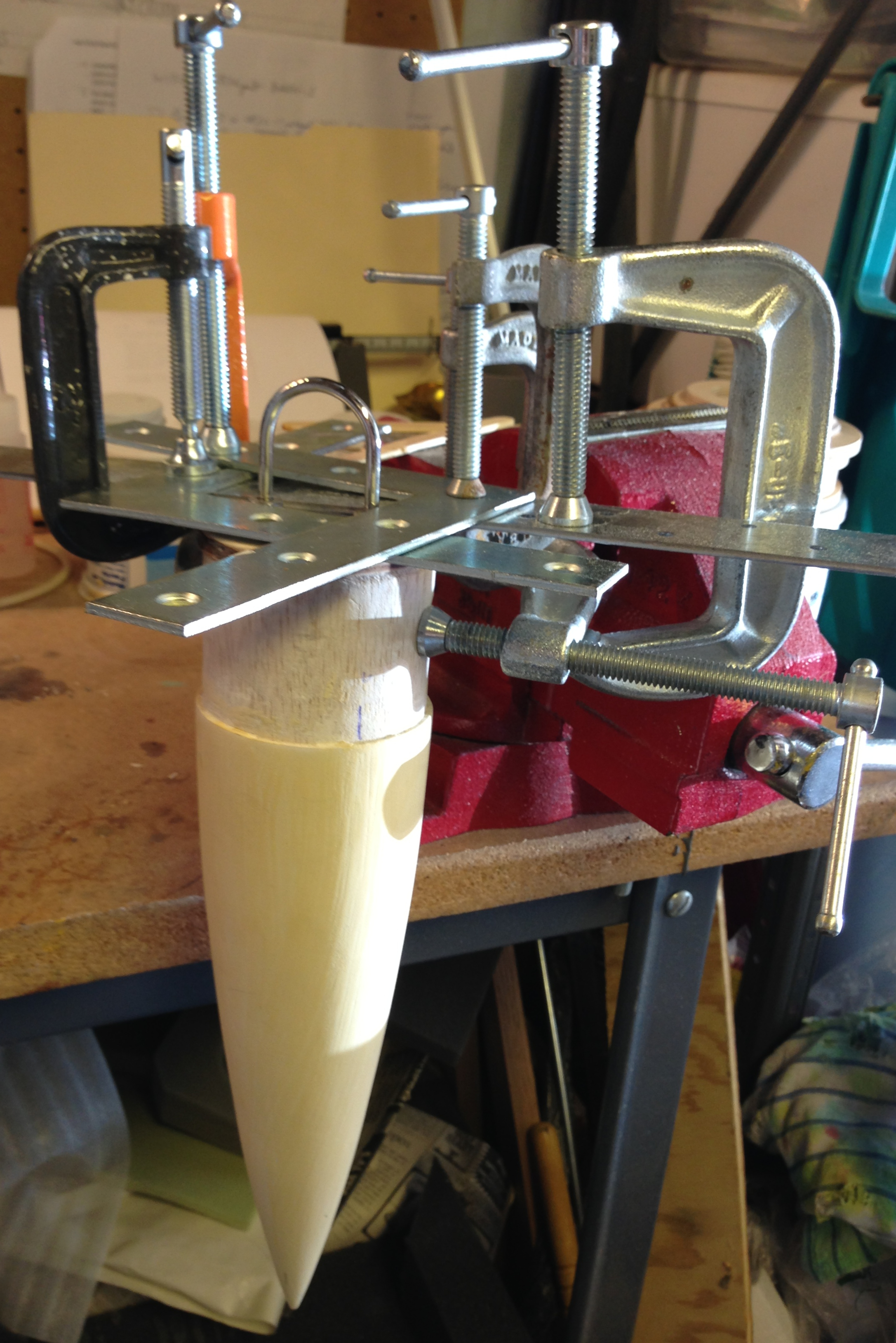
Nose cone and nose baseplate assembly mating
Most of the recent work has been on BAAH-1’s paint prep. Not quite all, but most.
The balsa nose cone takes an enormous amount of work to get it as smooth as I want it. I don’t need a polished hardwood furniture-grade finish on it, but I don’t want all the lathe pits and typical balsa deep gouges filled. I’ve been using Pactra balsa filler coat and diluted Elmer’s wood filler, with a healthy amount of elbow grease and sandpaper mixed in. At left is the nose cone in filler coat.
I felt that the balsa wood of the nose cone would not be as strong as I wanted for retaining the recovery harness U-bolt. I decided to attach the U-bolt to a bulkhead, then epoxy and glue the bulkhead to the base of the nose cone. Though this would add weight, it would be much stronger, I felt. The picture at right shows the nose cone and its baseplate assembly, with the whole thing in a clamp mechanism. (Note that I changed from the balsa filler coat to the diluted wood filler between these two pictures.) To get everything to fit flush, I had to remove some of the base of the nose cone, in order to provide a channel for clearing the U-bolt mounting hardware.
The final result of the baseplate addition, along with another coat of wood filler, is shown in picture below right.
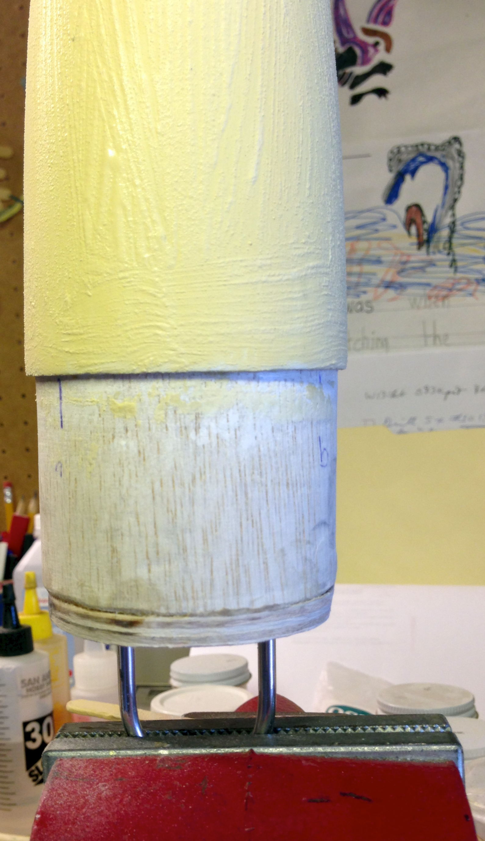
Nose cone assembly complete; another coat of dilute wood filler applied.
I really do want the finish on this rocket to be nice. I’m going as far as borrowing a technique from my Saturn V: filling the spiral wind grooves in the airframe tubing. See the blog entry from mid-May 2009 (“Primed!”) for a picture of this (both before priming and after, for a quick comparison). There’s an incredible amount of sanding needed to get everything smooth, but I figure it’s worth it. Besides, I’m modeling a smooth surface with no spiral winds, and if I’m going to the trouble of ½” eye bolts for launch guides in order to be historically accurate, I’ll certainly fill the spirals, and get the nose cone looking somewhat nicer than balsa (I’m modeling a wood nose cone, so it needn’t be perfect, but it takes a lot of work to get balsa even close to smooth!).
As to those eye bolts, I realized I had another problem with the launch guide issue. I had one eye bolt near the forward end of the rocket, and one nearly fully aft. Once the forward eye bolt left the launch rod, the launch guidance was gone: nothing would keep the rocket aligned, since the eye bolt can pivot, at least a little, around the rod. The only solution, while still maintain what I’ll call historical mission accuracy (i.e., launching off a rod, not a rail) was to add something well aft to maintain alignment. I decided to add the capability to install additional eye bolts during launch prep. By going to three eye bolts at the aft end, I was essentially building a launch lug assembly. Unfortunately, with the motor mount now fully installed, accessing the area for the backing nuts for these two eye bolts was difficult. Possible: they’re aft of the mid centering ring. But difficult.
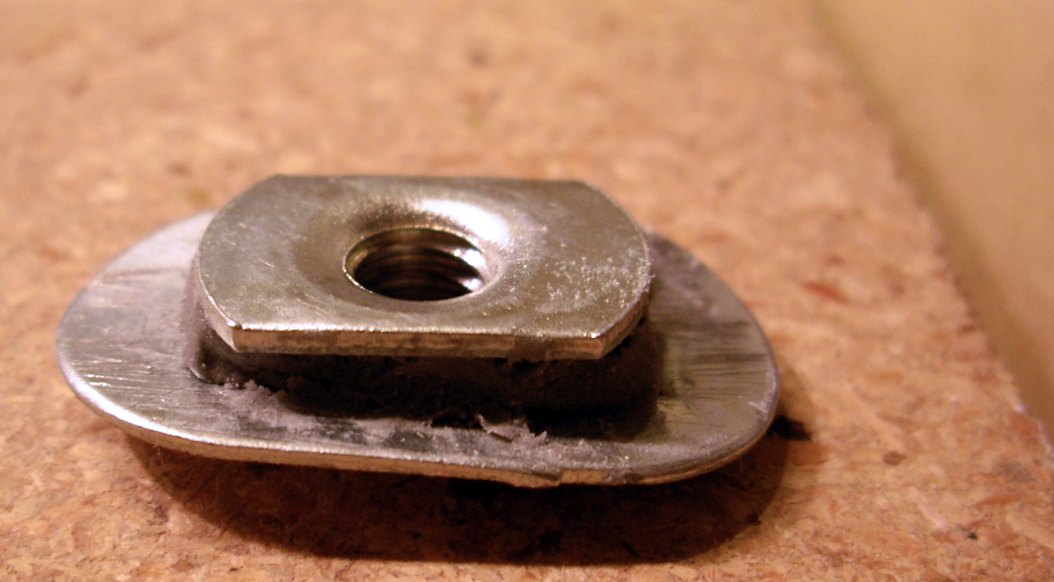
Blind nut for forward eye bolt, with conformal washer
Backing assembly for the forward launch guide eye bolt.
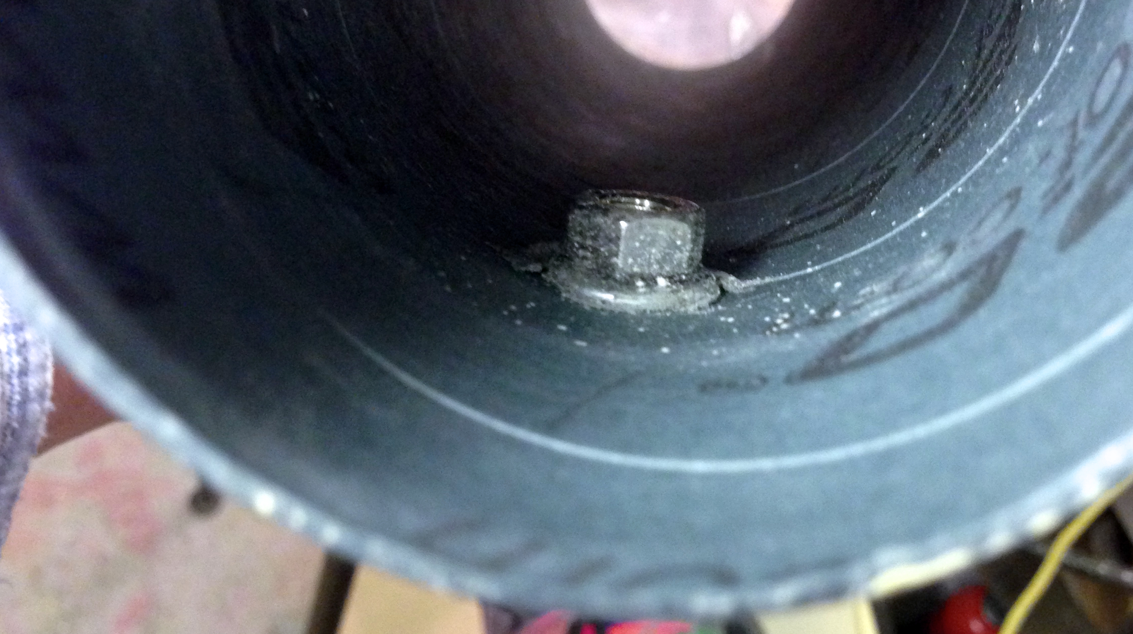
Below left is a a backing nut assembly for the aft eye bolt launch guide. As with the previously-installed launch guide backing nuts, I wanted a roughly-conformal surface for the epoxy between the assembly and the body tube. I used some epoxy putty to secure things, and could then epoxy the assembly to the inside of the airframe. You might wonder why I used the odd-shaped nut. Because I had already installed the motor mount, I knew it would be a challenge just to get the assembly properly positioned and held while I secured it (I screwed it down with a ¼”-20 machine screw and a jam nut on the opposite side of the airframe wall). I happened to have both the oddly-shaped T-nut and the similarly-shaped washer, and they seemed to fit the bill nicely, giving me the right sort of surfaces for grabbing with needle-nose pliers while holding it in place and securing it. On the right, then, is a picture of the assembly in place: you can see just how tight a space that is.
What about the forward eye bolt? It was straightforward: curve a regular stainless flat washer, epoxy a stainless nut and washer together, let them cure, then epoxy the assembly to the inside wall of the airframe. I used the same positioning technique as described above.
On to the fins!
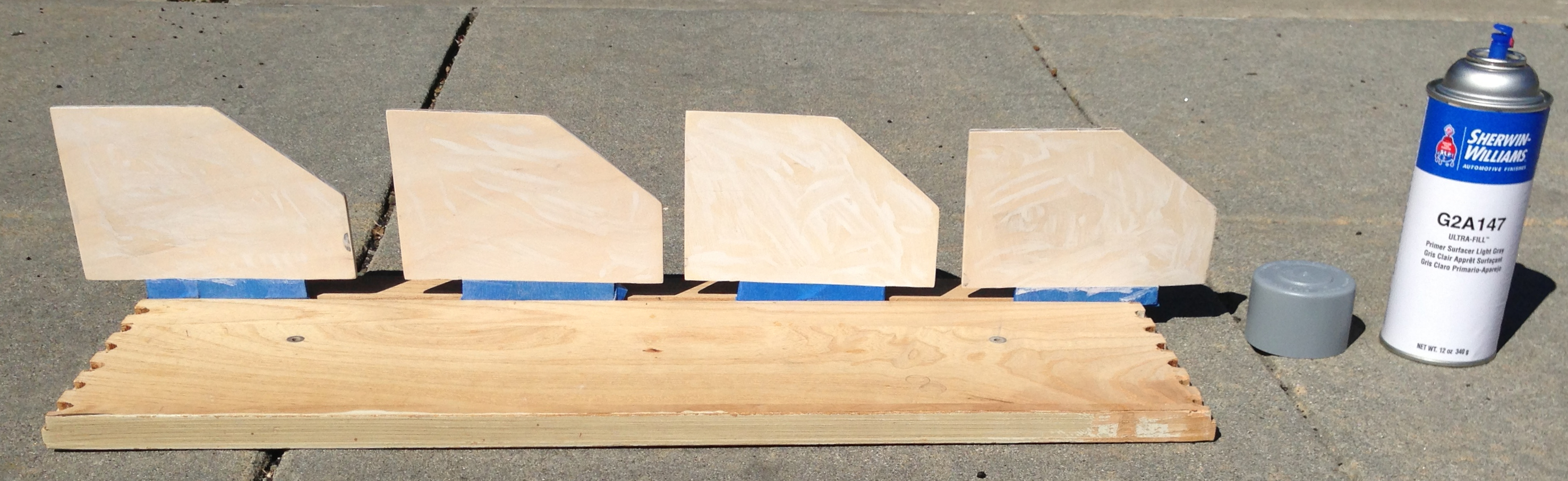
Fins in the paint jig, ready for priming.

First couple of coats of primer complete.
The picture at left shows the fins before priming; on the right, after a couple of coats of prime have been applied. I’m not certain how many primer coats I’ll end up using.
The jig holding the fins upright for painting is the front of a dresser drawer that I salvaged from somewhere: I don’t recall where. The groove in the drawer front happens to be just about a perfect fit for the fin tabs with some tape to mask them off. Pure happenstance, but I’ll take being lucky when I can can get.
It happened to be a nice warm day for this time of year (March 2013!) that Saturday afternoon when I was able to prime. Just about perfect conditions for painting, though I would have preferred a little less breeze.
…
It’s now nearly a year after I first drafted this, nearly a year of inactivity on the blog (other than the posting about the February LUNAR Snow Ranch launch!), nearly a year’s hiatus in building BAAH-1. Other aspects of life have intruded, not all of them bad (e.g., a wonderful family vacation to Alaska!). Soon, it will be back to the Rocketworks and BAAH-1.