Folie à Trois
It’s a another lunatic project. First, scratch-build my L-1 cert project (see these posts; yes, I finished the project, even though I’ve not written about the final build portions and flight: that will come). Then, repair and complete another 1:70 Saturn V, modeling AS-501 (aka Apollo 4), which has numerous differences from Apollo 11 (AS-505), the vehicle on which the model was based.
Now, scratch-build my first high-power cluster-capable rocket.
Not just any cluster. A sane first cluster project would be two motors, or three motors in a tight triangle. My first high-power cluster project has three motors inline, and will be capable of flying on one, two, or three motors. When it flies on three, it can be launched on one, two, or three motors through air-start capability. The rocket will also have dual deployment capability.
Two avionics bays, two computers. One computer will be used to control deployment, a second (either completely separate computer or a remote triggering device) to control in-flight motor ignition.
Sounds crazy, no? But, in our little village of Palo Alto…
Here’s the side view of the rocket design.


Base 29-100 Centering Ring
First Extra Hole Drilled
It’s a wholly conventional basic planform, 3FNC (three fins and a nosecone)—except for the fins, which have a bit of a flair to them.
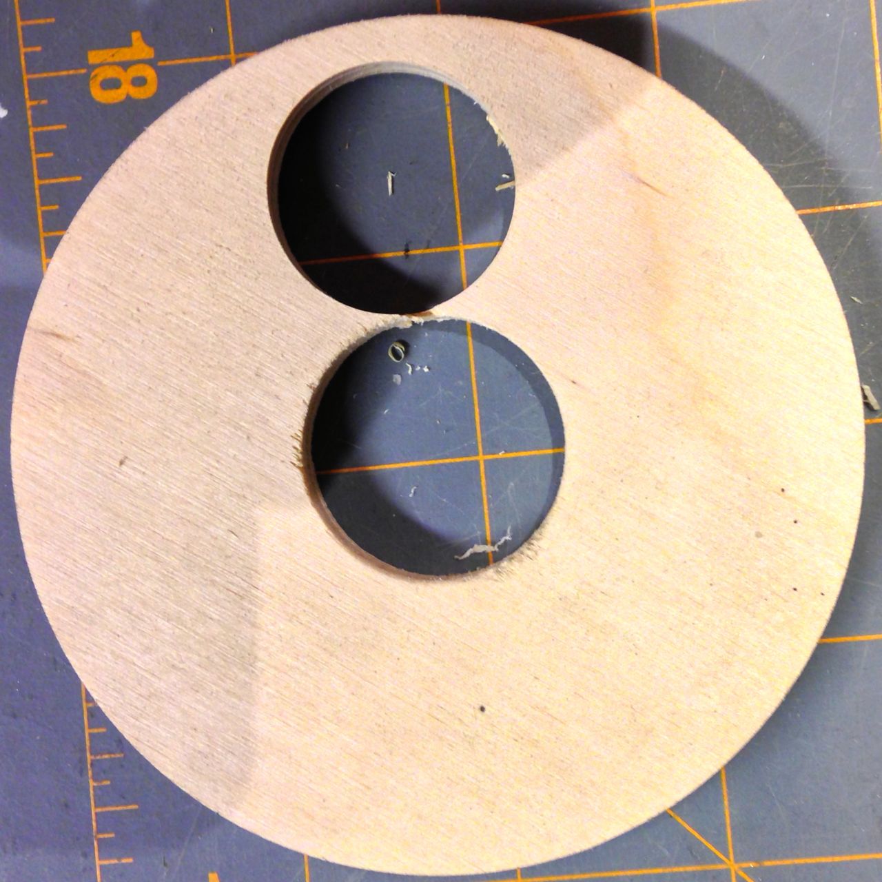
After designing the rocket (using RockSim), I figured a good next step was to start on the motor mount assembly. This was going to be one of the most complicated parts of the rocket. At the left is one of the starting points for the motor mount: an unmodified 29-100 plywood centering ring. At the right is that same CR with the first of two extra in-line holes drilled. I drilled out the hole using a 1⅛” Forstner bit, which comes out to about 28.5mm. That’s as close to 29mm that I could find, especially without going larger than 29mm. (Yes, I looked around: not just locally, but in various shops online. I couldn’t find a 29mm Forstner bit, at least not without it being part of a large set—at best. I really wasn’t interested in spending $50 just to get that one bit I cared about.)
All MMT Holes Drilled and Sized
CR Template
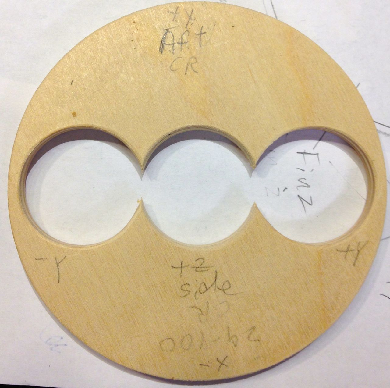
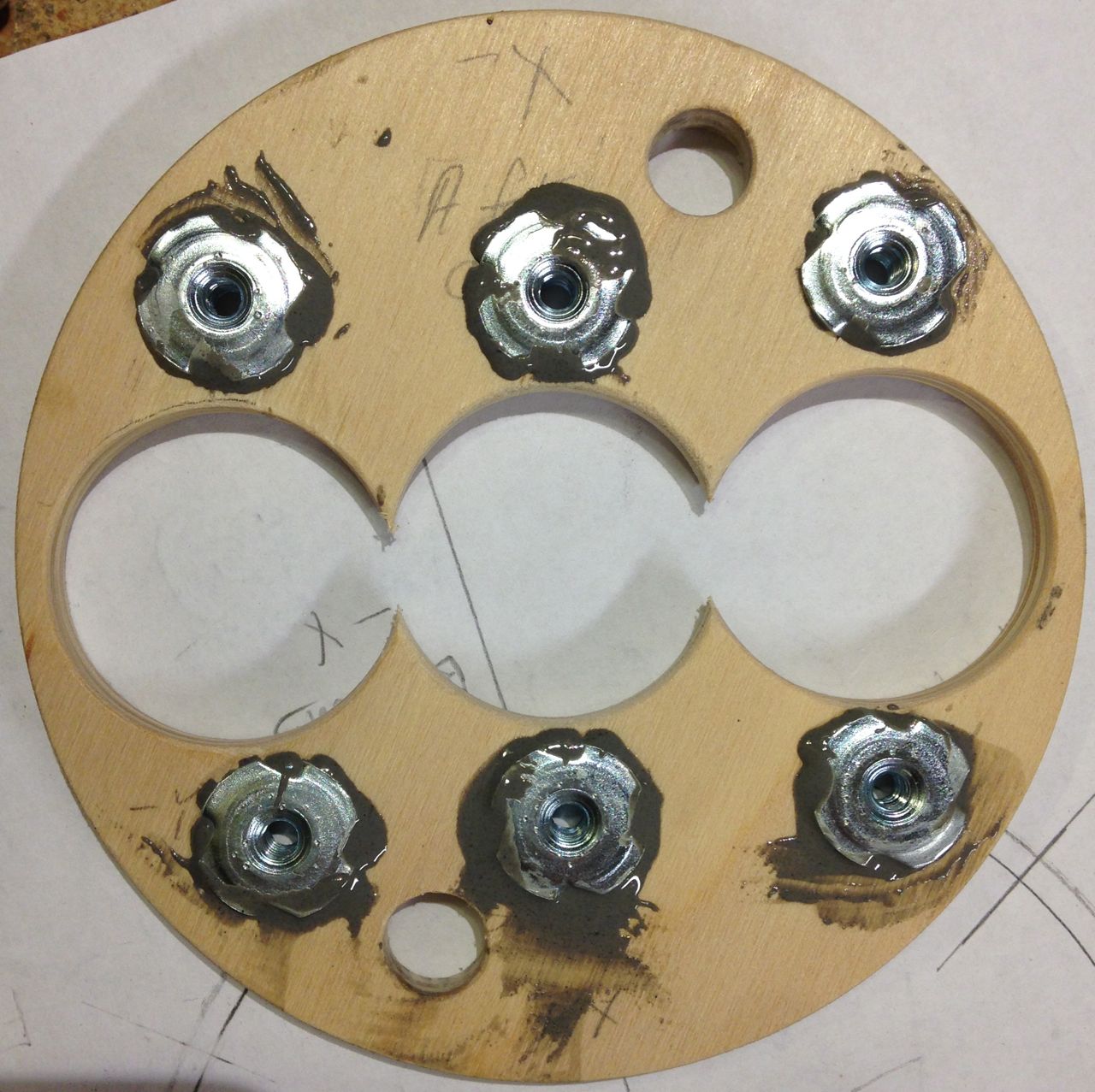
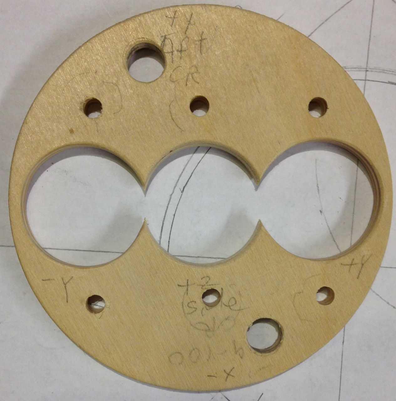
The most important tools were my drill press, that Forstner bit, and the CR template from RockSim. With the template, it was easy to locate the centers of the two outboard MMT holes, since each has its center marked (see the image to the left). You can see that template in the image to the left. To the right, the CR with the three MMT holes drilled, and sized. I did the final sizing (enlarging the 1⅛” holes to 29mm) again using the drill press, this time with a cylindrical abrasive sanding bit: sand a little, test fit, sand a little, test fit… (Note the coordinate markings in the drilled CR. More holes will be drilled, and I wanted to keep the orientation correct, along with that of the motor mount assembly in the airframe. Aligning a three-abreast motor mount with three through-the-wall fin tabs isn’t trivial.)
Motor Mount Unglued
Blind Nuts Epoxied
MMT, Blind Nut, and Igniter Tunnel Holes Drilled
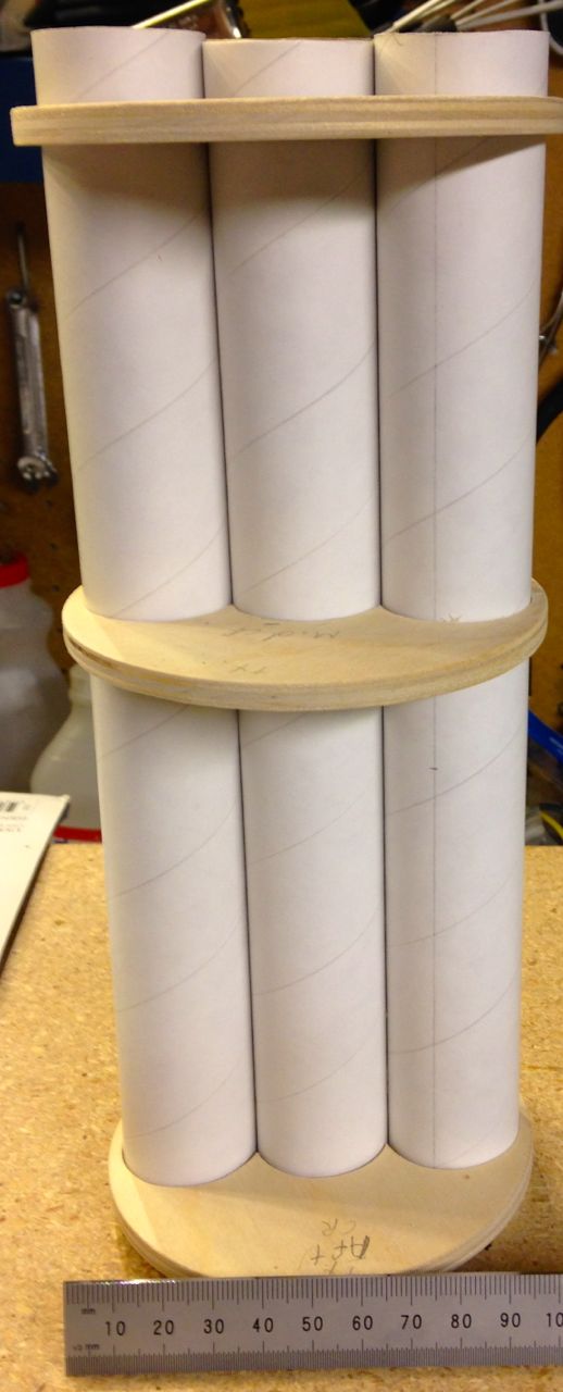
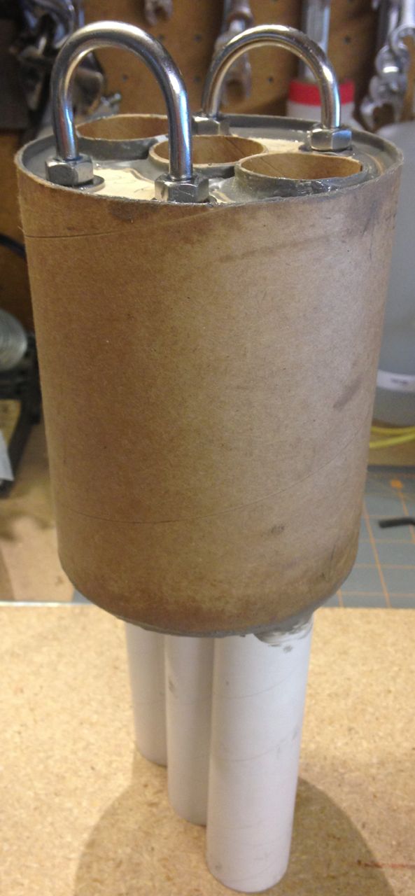
At left are the motor mount tubes and centering rings assembled for a test fit.
On the right, you’ll see the extra holes drilled in the aft CR. The two holes closest to the edge are for igniter wire tunnels. I’ll put an aluminum tube through each, to also run through identical holes in the mid CR. Igniter wire will then be able to run from the computer module in the aft avionics bay that will live between the forward and mid CRs, down to the motors for air start ignition.
The other six holes are for blind nuts (aka t-nuts), which I’ll use to hold the motor retainers in place. I plan to use window screen retainers fur the purpose: they’re inexpensive, light, and will fit given the motor layout (whereas something like an AeroPak retainer won’t fit). Further to the right right you’ll see those blind nuts epoxied in place.
Finally, time to start the real assembly of the MMT.
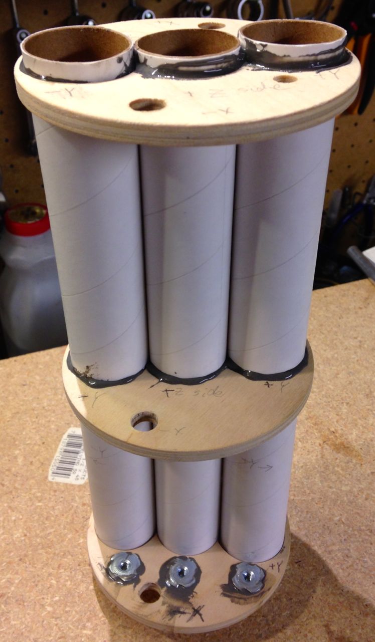
Fwd and Mid CRs Glued
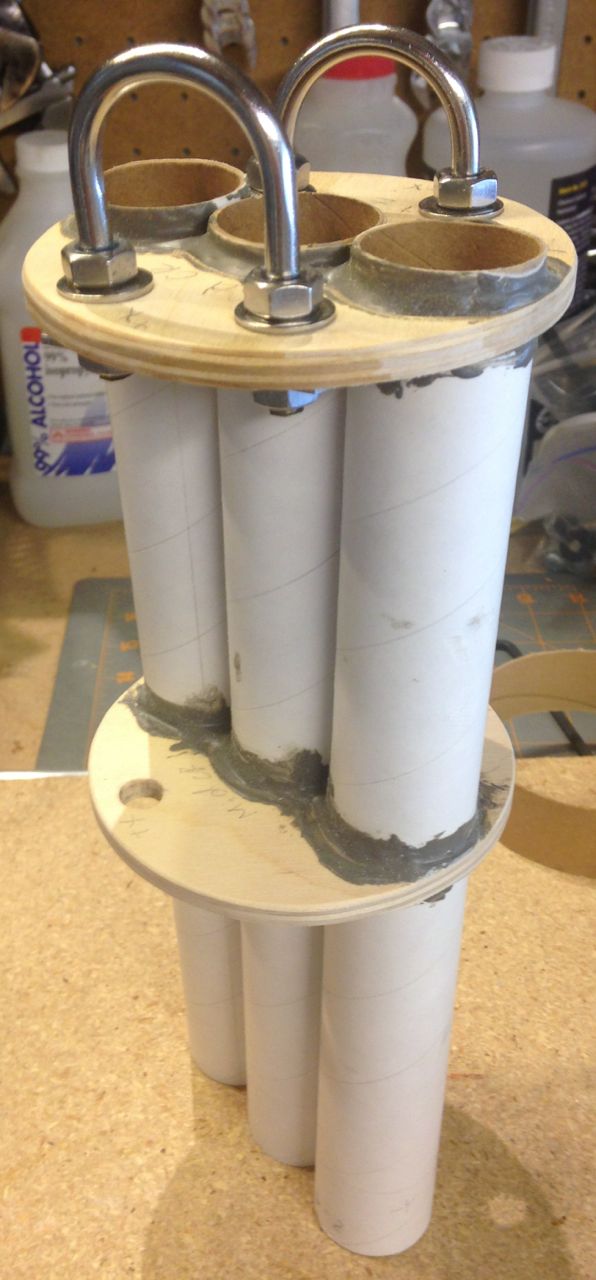
U-Bolts Added
Left: the forward and mid CRs are epoxied in place (with JB Weld), and the aft CR is placed as a support. The aft CR will be attached after the motor mount and fins are installed, positioned flush against the aft edges of the TTW fin tabs.
I’m using a pair of u-bolts to attach the recovery harness to the forward CR. Though I’m sure this is gross overkill—two u-bolts instead of one, or instead of a single lifting bolt—the pair will help even out the forces on the rocket. In the picture on the right you can see the u-bolts attached. These will not need to be removed, so I used a high-strength thread locker to secure the nuts to the u-bolts.
Once everything dried, it was time to add the housing for the avionics bay. That housing—a tubing coupler—presented its own challenges. Not because of the housing or the design, but because of my implementation.
Avionics Bay Added
I put it on at the wrong time.
The centering rings are sized to fit into the airframe. So is the tubing coupler. In other words, the CR and the TC have the same diameters. Since the TC’s wall is about 1mm thick, the CRs are too big to fit inside the TC—by about 2mm. Once I decided how to handle this, it wasn’t a difficult problem to solve. With the help of a new belt sander, I reduced the diameter of the forward and mid CRs so the TC would fit. Then, it was a simple matter of epoxying everything together.
Next up: cutting the hatch (door) in the aft avionics bay. I plan to cut the hatch in the TC slightly smaller than that in the airframe and glue them together for a bit of extra strength.
Stay tuned.