…Houston, We’ve Had a Problem—the Hex Nut and the MMT
So many clichés.
- The best laid plans…
- Measure twice, cut once.
- Missed it by that much.
- A miss is as good as a mile.
- And the grandaddy of all rocketeers’ clichés: Okay, Houston, we’ve had a problem. (This one is famously mis-quoted.)
The problem is hardly as life-threatening as that experienced by Lovell, Swigert, and Haise. It didn’t take as long to fix, nor did I have to be as creative as those in Houston to solve the problems facing that crew.
First, some of what’s occurred since my last post on BAAH-1.
Finding the right U-bolt for attaching the recovery harness to the forward CR wasn’t quite trivial. That ring is pretty narrow: the MMT is 38 mm, the airframe is about 65, resulting in the CRs being only about 13 mm wide. Finding a U-bolt that fit inside the airframe and outside the MMT, with mounting hardware (washers and nuts) that clear the MMT and the airframe, and providing enough strength that I’m happy with the affair, and, ideally, made of stainless (since it will be exposed to the ejection gases and completely inaccessible once the rocket’s built, because of depth in the airframe) took some work. Eventually, I found a 4 mm stainless U-bolt at a marine supply company.
As I pondered the situation, I came to feel that the CR might be a little on the thin side to be as strong as I wanted. I happened to have an extra CR, so I decided to double the ring. Almost certainly overkill…
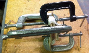
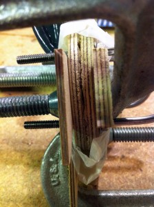
At left and right are pictures of those two rings glued together and clamped for drying, to form the forward CR and recovery harness anchor point. In order to avoid putting a big dent in the final CR, I grabbed some scrap wood to use between the C clamps and the CR, with a little wax paper in strategic places just in case some glue somehow seeped out. I cut down some extra length on the U-bolt legs, too, after the glue dried.
Next up, install the mid CR on the MMT. Again, a little wax paper helped ensure I didn’t epoxy the whole assembly to the vice that held the MMT upright while the epoxy set.
Time now to unknowingly create the beginning of my problem.
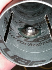
The plan all along, carefully thought through, has been to insert the MMT from the aft end of the rocket, use the aft CR to align things long enough for me to install the forward CR (but not yet epoxying the aft CR in place), then let the epoxy set with the rocket upright. If I applied the epoxy correctly to the inside of the airframe, this would provide fillets in the two areas I would be unable to access once the MMT was installed in the airframe. To do this successfully, I needed to install the hex nut securing the aft launch guide after installing the MMT, even though reaching in between the MMT and the airframe would be difficult. I even included this in the build guide I wrote for myself.
Did I refer carefully to the sequence of steps in the build guide? Nope. While the mid CR’s epoxy was setting, I installed the hex nut for the aft launch guide. I think I did a nice job, bending a washer to conform to the curve of the airframe’s inner wall, getting it placed and epoxied without gumming up the threads, etc. Only problem was that the nut now blocked installing the MMT in the way I had planed.
Feh.
I didn’t realize the problem immediately. Instead, I set out working on other tasks while all this epoxy set. These tasks included, among other things, attaching the recovery harness to the forward CR’s U-bolts. This, too, presented some small design issues. I have a nicely woven piece of Kevlar® to run from the anchor point to the parachute’s quick link. The Kevlar has a loop sewn in each end. The loop doesn’t fit over the double U-bolt system, and a quick link big enough to go between the U-bolts for the Kevlar sewn loop would be very large. I didn’t want to skip this double U-bolt system.
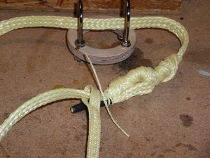
I have some ½” woven Kevlar cord, so I made a harness adapter, using a blood knot to make a loop that goes through everything. (The ends are dressed with heat shrink tubing, to keep them from unraveling—probably a vulnerable point in the whole harness—and dressing the ends with some thin Kevlar cord.
All set. Time to install the MMT, including the forward CR.
This is when I discovered the problem of that hex nut blocking installation of the MMT assembly.
At least I realized the problem before I mixed up the epoxy (much less, applied it to the airframe!). There was a chance I could work around the problem, though I wouldn’t have that optimal filleting: just insert the MMT assembly from the forward end of the airframe. In order to be able to get the epoxy applied inside the airframe for the forward CR, I would apply the epoxy and slide the forward CR onto the MMT after inserting the MMT assembly and positioning it. I tested this out in a couple of dry runs, and it seemed like it would work fine.
But, it didn’t.
Initially, I thought it had worked. The MMT assembly went in just fine, it ended up in the right position, and the forward CR’s epoxy and installation went without apparent problem. After filleting the forward joint between the airframe and the forward CR, I examined the installation carefully, peering waaay down inside the airframe, as I got ready to filletand clearly saw that the forward edge of the MMT was not visible beyond the CR. In fact, I could see what I thought was a lip. I little probing with a long rod confirmed this. The epoxy equivalent of a cold joint on a circuit board. I thought about this, tried to push the CR down, jiggling the MMT a bit hoping to improve the alignment (in case that was the problem), and realized I couldn’t budge that CR.
I set everything to cure, pondering the problem overnight.
I thought about leaving everything alone, figuring that, perhaps, the CR-airframe joint would be strong enough to hold everything together, and the two CRs around the fins would keep the MMT secure. I decided I wanted to get this right.
I thought about dumping enough epoxy into the cold joint to bond the ring to the MMT, using a stick or rod to get the epoxy down to the joint.
I thought about cutting the airframe several centimeters forward of the ring, so I could look at the joint, then reassembling the airframe with a tubing coupler at the joint when the repair was complete.
I decided I should cut and repair the airframe.
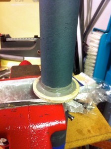
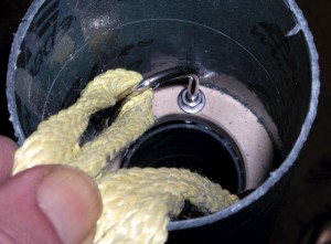
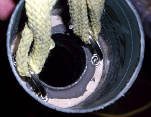
Out came the miter box, open came the airframe (cutting carefully: I had to cut around the airframe, not straight through it, unless I carefully tucked the lower portion of the recovery harness deep into the rocket). The pictures show the situation, first before, then after repairing the cold joint. They don’t tell quite the whole story, unless you have a very sharp eye (or examine the full-size pictures carefully). Rather than simply throw epoxy into the cold joint, I started thinking about other options. I had cut the MMT down (initially, about 120 cm, using 75 cm in the rocket, to ensure adequate room for the parachute and any avionics bay I might install later). This left me with a nice piece of 38 mm MMT tube; I also happened to have an appropriately-sized tubing coupler, even though I didn’t expect to need it. What about, then, using the coupler and a small piece of the 38 mm tube to extend the MMT out through the forward CR? This seemed like a good option, but I wanted others.
I also considered just using the tubing coupler, without adding the 38 mm tube. This had the advantage of not having to fit the 38 mm tube inside the hole in the CR, which might have proven difficult given the slightly flawed alignment. It would also be easier to get the coupler into the CR than to get the larger 38 mm tube into it, since the coupler was slightly smaller.
I decided on using just the coupler, and to apply enough epoxy to fill the gap between the coupler and the CR. This would also provide a good, solid fillet.
The picture at left shows the result. It looks like the repair turned out pretty well.
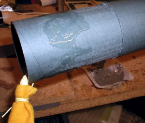
Last bit of the repair: reassemble the airframe. That was pretty straightforward, since I had an extra coupler for the airframe tubing. The picture below shows an intermediate stage of this portion of the repair: the coupler’s epoxied into the lower segment of the airframe, and the protruding portion of the coupler has epoxy applied, ready to be joined with the upper portion of that airframe tube.
I also took the opportunity afforded by access to the lowest portions of the recovery harness to add a Nomex® shock cord protector. This is the darker yellow sleeve around the shock cord, secured by some Kevlar cord. It’s not complete protection for all the lower portions of the harness, since the ½” inch Kevlar loop through the U-bolts is unprotected, but it’s still better than it was before.
Remaining in this bit of the repair: fixing the cosmetic damage inflicted by sawing the tube in half. I’ll do that when I fill the spirals in the airframe tubing, prior to painting.
