BAAH-1 Update: Fins Done, Airframe Slotted
Work continues, albeit slowly. At this point, the fin slots are cut in the airframe and fit to their respective fins and the fins are finished. I need to drill a few holes (launch lugs and rail buttons), start to build the motor mount, and begin the motor mount installation.
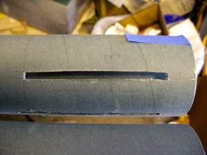
Close up of airframe fin slot.
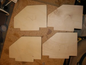
Four fins all set: properly sized, sanded, etc.
Getting each fin slot to fit its respective fin was not difficult, merely a little tedious. I wanted each slot to fit just right, probably more than a little overkill.
If you have a sharp eye and compare the picture to the left with the picture in my earlier post, you’ll notice the fin slots are now shorter than they were. My original design did not take into account the Aero Pack motor retainer, and I needed more space at the aft end of things. Not hard to trim the tabs and, in fact, they’re closer to really squared up than they were.
Also, if you look closely, you’ll see each fin numbered, to correspond to its slot in the airframe. Again, perhaps overkill, especially since I want all the tabs to be the same length, in order to butt properly against the CRs (one will be at each end of the tabs).
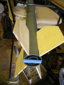
All four fins slid (but not epoxied yet) in place. Note the tape holding the MMT in.
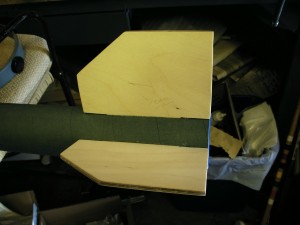
Side view of fins 1 and 4 slid into place.
At left is a shot of two fins—fins 1 and 4—slid into place; all four fins are shown to the right. In order to ensure the tabs are the right length, I temporarily “installed” the MMT. It’s not epoxied, just placed in with its unepoxied centering rings to align in, then kept from sliding out with a couple pieces of tape to act as fences.
Next up, it’s time to drill the airframe for the launch lugs (eye bolts, forward and aft) and the rail buttons (forward, mid, and aft). I was delaying drilling while I figured out whether I could use the same holes, but I can’t find an eye bolt with a large enough eye (½” plus some clearance) that used the same thread as the rail buttons (#8, if I recall correctly). The answer: no, I need separate holes (rats!).
The motor mount needs, first, the mid CR attached to the MMT. I’ll then install the motor mount, sliding it in place from the aft end and then affixing the forward CR (this will allow for the simplest installation, given epoxy application, and also allow me to apply fillets on both sides of all CRs). The forward CR will have a couple of small U-bolts installed: I managed to find some M4 stainless U-bolts (4mm shank diameter), and this small size will allow for smaller holes and a stronger CR. Since the U-bolt won’t span the CR’s 38mm inside diameter, I’m using a pair opposite each other, and I’ll run the shock cord through both bolts. Though the U-bolts will fit just fine as-is, they’re longer than I need, so I’ll to cut them down.